


Drawing overview
- What are vector graphics?
- Drawing tools
- Shape or a path?
- Converting shapes to paths
- Changing the corner radius
- Combining paths
- Compound paths
- Clipping paths
- Opacity masks
Microsoft® Expression Blend™ offers standard vector drawing capabilities so that you can draw shapes, paths, and masks just as you would in any vector graphics program. For more advanced drawings and artwork, consider using an alternative vector graphic program such as Microsoft® Expression® Design. Expression Design even offers the ability to export drawings as XAML for use in Expression Blend.
What are vector graphics?
Vector graphics are defined geometrically by points, lines, curves, and surfaces, rather than by pixels as within a bitmap. As monitors for computers incorporate higher resolution displays, there is a need to move away from bitmaps, which show large pixels when viewed at a high dpi. The resizing of bitmaps can be awkward, and they generally lead to poor quality graphics. Vector graphics remain smooth when viewed at a high dpi, and remain crisp when resized larger. For this reason, vector graphics are easier to customize around content, because you do not have to create multiple images at different sizes—for example, icon files that appear in the user interface (UI) at various sizes. Other beneficial implications of vector graphics include the following:
- True content scaling Vector graphics built into flexible layout can resize elegantly based on content. For example, when you add text to a button, the button will resize accordingly without compromising the fidelity of the graphic.
- Resolution independence The resolution of displays has been gradually increasing and will likely continue to do so. Without the ability to scale an application's UI, the UI simply becomes smaller as the resolution increases, typically becoming unusable when the content appears so small it becomes unreadable. If you apply a scaling or rotation transform with these APIs, it only affects the drawings. There is no effect on the sizes and positions of controls in the window. You can scale drawings, but you can't easily scale the way that a window's space is carved up by controls. Because Windows Presentation Foundation (WPF) composes all of the controls in the window as a single drawing, rather than segregating each control to its own region, it is easy to apply scaling or rotation transformations to the UI as a whole. Thus, since you can scale any WPF UI up or down, WPF applications are effectively resolution-independent. Images remain sharp and clear, as opposed to the blur you would expect from simple bitmap scaling.
|
|
When setting size-related properties in Windows Presentation Foundation (WPF) applications (like those created with Expression Blend), pixels refer to device independent pixels or device independent units which are equivalent to the size of a pixel on a monitor that is set to a screen resolution of 96 DPI. Each unit is approximately 1/96 inch, regardless of monitor size or screen resolution. |
In Expression Blend, a vector object can be as simple as a line or shape, or as complex as a path or control. Objects can be modified in many ways using on-object handles for resizing, moving, rotating, flipping, or skewing objects, or using the Properties panel where you can enter precise values for size, position, and rotation. Basically, every object you draw onto the artboard is in vector format except for those items that you've added to your project that weren't originally in vector format, such as images and 3D textures. Some of the vector objects in Expression Blend include:
- Drawing objects such as an ellipse and rectangle
- Path objects such as lines and curves
- Text
- 3D objects
- Controls
Drawing tools
In the Toolbox, you'll find common vector tools for creating shape and path elements, and for manipulating objects. For examples of using these tools, see Draw a shape, Draw a straight line, Draw a curve, Draw a freeform path, Change the shape of a curve, and Redefine handles for a node.
| Tool | Use to | |
|---|---|---|
|
|
Rectangle | Draw rectangles and squares, which can also be modified to have rounded corners. |
|
|
Ellipse | Draw ellipses and circles. |
|
|
Line | Draw a straight line between two points. |
|
|
Pen | Draw and modify paths where you define each node. The Pen tool allows you to add, remove, and modify nodes within the path. |
|
|
Pencil | Draw freehand paths. |
|
|
Selection | Select shapes, paths, and objects on the artboard that you want to modify. For more information about using the Selection tool, see Select an object. |
|
|
Direct Selection | Select individual nodes on a path after they have been drawn. The Direct Selection tool also enables you to directly select child objects nested inside a parent object on the artboard, such as a layout panel. For more information about using the Direct Selection tool, see Select an object. |
Shape or a path?
Shapes such as a rectangle or ellipse are vector objects. You draw shapes
with the Rectangle
![]() or Ellipse
or Ellipse
![]() tools.
tools.
Paths are also vector objects—arguably the most flexible vector objects in Expression Blend.
Paths are a series of connected lines and curves. After drawing
paths onto the artboard, you can
reshape, combine, and otherwise modify them to create any vector shape. You can
draw polygons, which are closed shapes made up of straight, connected lines, as well as polylines,
which are unclosed paths made up of straight, connected lines. You draw paths
with the Pen
![]() ,
Pencil
,
Pencil
![]() ,
and Line
,
and Line
![]() tools. You can then
use the Selection
tools. You can then
use the Selection
![]() and Direct Selection
and Direct Selection
![]() tools for modifying paths. For more information about modifying paths, see
Delete part of a path, Add or remove a node on a path,
Change the shape of a curve, Redefine handles for a
node,
Pen and selection shortcuts.
tools for modifying paths. For more information about modifying paths, see
Delete part of a path, Add or remove a node on a path,
Change the shape of a curve, Redefine handles for a
node,
Pen and selection shortcuts.
Converting shapes to paths
Shapes cannot be edited the same way as path elements unless you convert the shape element to a path element using the Convert to Path command (Object | Path | Convert to Path). For an example, see Change a shape into a path.
|
|
You will not be able to edit properties that are specific to a shape (such as the corner radius of a rectangle) after converting the shape to a path. Also, if a style was applied to the shape before conversion, the properties of the converted path will be reset to the defaults for a path (no fill brush, and a black stroke). |
Changing the corner radius
You can edit the corner radius of a rectangle by selecting the rectangle and
then dragging the corner
radius handles on the upper left corner.
The corner radius handle
 appears when your mouse pointer moves over either end of the dotted lines that
jut out from the top left corner of the rectangle.
appears when your mouse pointer moves over either end of the dotted lines that
jut out from the top left corner of the rectangle.
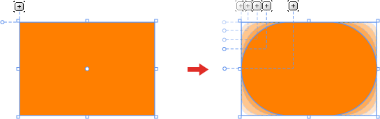
By holding down SHIFT while you drag either corner radius handle, you can edit the X and Y corner radii individually.
For an example, see Round the corners of a rectangle.
Combining paths
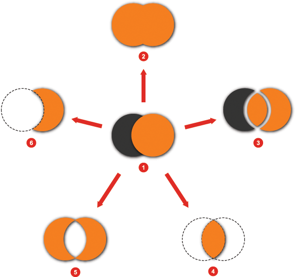
Combining paths (or shapes) can provide you with the following results:
|
|
Two shapes before combining |
|
Intersect | |
|
|
Unite |
|
Exclude Overlap | |
|
|
Divide |
|
Subtract |
Two or more objects (paths or shapes) can be combined into one path object. The resulting path object will replace the last object that was selected before combining, adopting that object's properties. Often, the result is a compound path. For an example, see Combine shapes or paths. For more information about editing paths, see Pen and selection shortcuts.
|
|
You will not be able to edit properties that are specific to a shape (such as the corner radius of a rectangle) after combining. Also, if a style was applied to the last selected object before conversion, the properties of the combined path will be reset to the defaults for a path (no fill brush, and a black stroke). |
Compound paths
When you create a compound path, any intersecting portions of the paths are subtracted from the result and the resulting path takes on the visual properties of the bottommost path.

Two paths converted to a compound path
Shapes must be converted to paths before being included in a compound path (Convert to Path under Path on the Object menu). Two or more paths can be made into one compound path. The resulting path will replace the bottommost path (in Z-order) that was selected before compounding, adopting that path's properties. You can break apart a compound path any time after you create it, however the original properties will not be restored. For an example, see Make or release a compound path.
Clipping paths
A clipping path is a path or shape that is applied to another object, hiding the portions of the masked object that fall outside of the clipping path.

Image object with a clipping path applied to it
For an example, see Apply or remove a clipping path.
Opacity masks
An opacity mask can be a path or shape that is applied to another object. The transparent portions of the path represent areas where the masked object is faded out, whereas the opaque portions of the mask indicate where the masked object is allowed to show through. Any object can have an opacity mask defined for it through the Appearance section of the Properties panel.
An opacity mask can be a simple gradient brush that shows or hides portions of an object based on transparency. In the example below, the image on the left has no opacity mask applied, and the image on the right could be produced in one of the following two ways:
- The OpacityMask property of the Image object could be set to a radial gradient brush with the Alpha of the right gradient stop set to a value of 0.
- A Rectangle object could be created in front of the Image object, and the OpacityMask property of the Rectangle could be set to a radial gradient brush with the Alpha of the left gradient stop set to a value of 0.

Image with no mask (left) versus image with opacity mask applied (right)
For an example, see Create an opacity mask.